
An aircraft having radar stealth characteristics would be able to fly nearly undetected and could be attacked only by weapons and systems not relying on radar. The concept was to build an aircraft with an airframe that deflected or absorbed radar signals so that little was reflected back to the radar unit. īy the mid-1970s, military aircraft designers had learned of a new method to avoid missiles and interceptors, known today as " stealth". It later served in Iraq, Afghanistan, and Libya. Though designed originally as primarily a nuclear bomber, the B-2 was first used in combat dropping conventional, non-nuclear ordnance in the Kosovo War in 1999. It entered service in 1997 as the second aircraft designed to have advanced stealth technology after the Lockheed F-117 Nighthawk attack aircraft. The B-2 is capable of all-altitude attack missions up to 50,000 feet (15,000 m), with a range of more than 6,000 nautical miles (6,900 mi 11,000 km) on internal fuel and over 10,000 nautical miles (12,000 mi 19,000 km) with one midair refueling. As of 2018, twenty B-2s are in service with the United States Air Force, which plans to operate them until 2032, when the Northrop Grumman B-21 Raider is to replace them. In 2008, a B-2 was destroyed in a crash shortly after takeoff, though the crew ejected safely. During the late 1980s and 1990s, Congress slashed plans to purchase 132 bombers to 21. The winding-down of the Cold War in the latter portion of the 1980s dramatically reduced the need for the aircraft, which was designed with the intention of penetrating Soviet airspace and attacking high-value targets. īecause of its considerable capital and operating costs, the project was controversial in the U.S. The total program cost, which included development, engineering and testing, averaged $2.13 billion per aircraft in 1997.
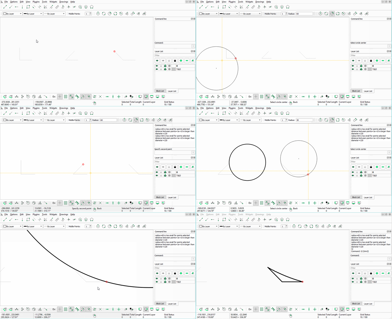
#DISPLAY CODE OF POINTS IN LIBRECAD SOFTWARE#
Total procurement costs averaged $929 million per aircraft, which includes spare parts, equipment, retrofitting, and software support. Designed and manufactured by Northrop, later Northrop Grumman, the cost of each aircraft averaged US$737 million (in 1997 dollars). Program costs rose throughout development. The ATB project continued during the Reagan administration, but worries about delays in its introduction led to the reinstatement of the B-1 program. The B-2 is the only acknowledged aircraft that can carry large air-to-surface standoff weapons in a stealth configuration.ĭevelopment started under the "Advanced Technology Bomber" (ATB) project during the Carter administration its expected performance was one of the President's reasons for the cancellation of the Mach 2 capable B-1A bomber. The bomber is subsonic and can deploy both conventional and thermonuclear weapons, such as up to eighty 500-pound class (230 kg) Mk 82 JDAM GPS-guided bombs, or sixteen 2,400-pound (1,100 kg) B83 nuclear bombs. Designed during the Cold War, it is a flying wing design with a crew of two. I used the List command in Rhino to display the endpoint coordinates.The Northrop (later Northrop Grumman) B-2 Spirit, also known as the Stealth Bomber, is an American heavy strategic bomber, featuring low observable stealth technology designed for penetrating dense anti-aircraft defenses. If the shape is open (points are not sufficiently coincident) then the CAM system cannot apply kerf (offset of the radius of the tool or plasma arc in this case) and the tool path will be centered on the the original lines and arcs rather than offset for the kerf, which would result in the part being cut to a slightly smaller size. Since I don’t know how their CAM systems works, it may be that the decimal accuracy need to be set in AutoCAD or in their CAM or nesting software. The problem I believe is that the CAM system is set to reject points that do not match beyond 10 decimal places or so. The values are consistent within 10 decimal places or so and that should be good enough for any CADCAM system generating toolpaths for CNC. That tiny gap typically not a problem and can happen for many reasons.

I suspect its not so much whether you see the gap, it is that the end point coordinates do not match. Although it still looks the same in Autodesk online viewer. I don’t in the Rhino file.Īnd here is a new dxf file made with ACAD 2000 instead of release 14. Here is a new Rhino file where I did a join. Seems as though LT2022 ought to give some kind of error message. Is there a way, if I can get time on their machine, where I can look at settings? I may end up taking my computer over and trying some different things but that seems a bit silly. I think they just got the LT2022 and it is running with whatever defaults it comes with. I’m afraid the CAM operator at the steel supply house is not an expert either.

Why should there be a gap in the dxf file? I am not an expert on these things. In my Rhino file the arc is an arc is an arc. Flipping the arc normals had no effect on the Autodesk online viewer.


 0 kommentar(er)
